Global web icon
wikipedia.org
https://en.m.wikipedia.org/wiki/Clamper_%28electro…
Clamper (electronics) - Wikipedia
A clamper (or clamping circuit or clamp) is an electronic circuit that fixes either the positive or the negative peak excursions of a signal to a defined voltage by adding a variable positive or negative DC voltage to it. [2]
Global web icon
geeksforgeeks.org
https://www.geeksforgeeks.org/digital-logic/introd…
Introduction to Clampers - GeeksforGeeks
Clamper shift an input signal by an amount defined by an independent voltage source. Typically, clamper circuits use a combination of diodes, capacitors, and sometimes resistors to achieve this effect. Clampers are also know as dc restores or clamped capacitors.
Global web icon
electricaltechnology.org
https://www.electricaltechnology.org/2021/10/clamp…
What is Clamper Circuit? Types, Working and Applications
A clamper circuit is also known as a clamping circuit is an electronic circuit that shifts the DC level of a signal without changing the shape of its waveform. It moves the whole signal either up or down about the reference level.
Global web icon
physics-and-radio-electronics.com
https://www.physics-and-radio-electronics.com/elec…
Clamper circuits - Positive clamper, Negative clamper and ...
A clamper is an electronic circuit that changes the DC level of a signal to the desired level without changing the shape of the applied signal. In other words, the clamper circuit moves the whole signal up or down to set either the positive peak or negative peak of the signal at the desired level.
Global web icon
tutorialspoint.com
https://www.tutorialspoint.com/electronic_circuits…
Electronic Circuits - Clamper Circuits
A Clamper circuit can be defined as the circuit that consists of a diode, a resistor and a capacitor that shifts the waveform to a desired DC level without changing the actual appearance of the applied signal.
Global web icon
electrical4u.com
https://www.electrical4u.com/clamping-circuit/
Clamper Circuit: What is it? (Diode & Voltage Clamping Circuit)
A clamper circuit, or clamping circuit, fixes the positive or negative peak values of a signal to a defined level by adjusting the signal’s DC value. This circuit type does not alter the peak-to-peak values but shifts the entire signal up or down to the desired level.
Global web icon
electronicslesson.com
https://electronicslesson.com/difference-between-c…
Difference Between Clipper and Clamper
A clamper, also known as a DC restorer or level shifter, is an electronic circuit designed to shift the entire waveform up or down without altering its shape. It achieves this by adding a DC component to an AC waveform, effectively repositioning the signal along the voltage axis.
Global web icon
electronicscoach.com
https://electronicscoach.com/clamper-circuits.html
What are Clamper Circuits? Definition, operating principle ...
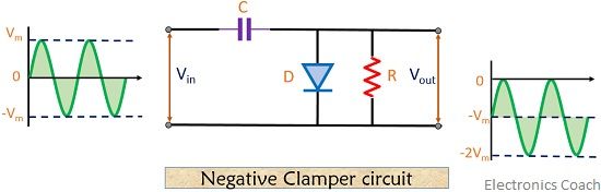
Definition: Clamper circuits are the electronic circuits that shift the dc level of the AC signal. Clampers are also known as DC voltage restorers or level shifter. Clampers are basically classified as positive and negative that includes both biased and unbiased conditions individually.
Global web icon
allaboutcircuits.com
https://www.allaboutcircuits.com/textbook/semicond…
Clamper Circuits | Diodes and Rectifiers | Electronics Textbook
Read about Clamper Circuits (Diodes and Rectifiers ) in our free Electronics Textbook
Global web icon
libretexts.org
https://eng.libretexts.org/Bookshelves/Electrical_…
3.4: Clampers - Engineering LibreTexts
A clamper is circuit that adds a DC offset to an AC signal in such a way that the resulting voltage is uni-polar. A positive clamper adds a positive offset such that the former negative peak now sits at zero volts.